Quantcast
Channel: Security Camera & Video Surveillance Blog
Viewing all 370 articles
Browse latest View live

What is the best BNC connector type?

$
0
0

Best BNC Connector

What is the best BNC connector? This article will discuss some of the most popular options that are available and present videos on how to connect these types of BNC connectors to coax cable.  I hope that it helps readers can decide which is the best choice for them.

BNC connectors are used in video applications with RG59 and RG6 coaxial cable. They are the industry standard connector for CCTV video surveillance systems. Almost always, devices such as CCTV cameras, surveillance DVRs, and security monitors have a BNC female video input or output on them. So, the coaxial cable that connects these types of devices needs to have BNC male connectors on both ends of the cable run.


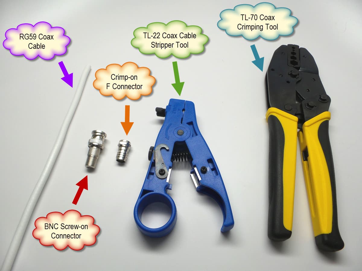
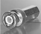
BNC Crimp-on Connector

BNC crimp-on connector
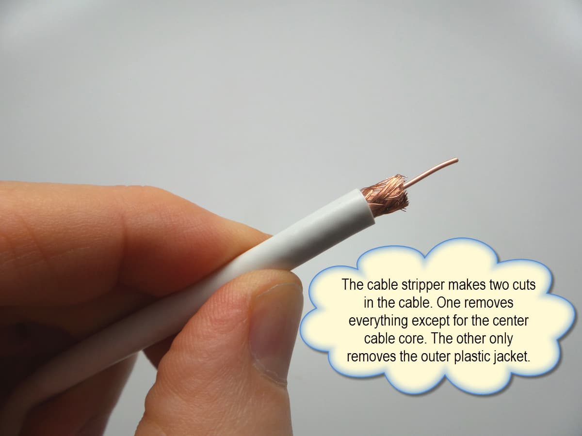
Crimp-on BNC connectors are available in two styles: 2 piece and 3 piece. The two piece style is much more popular, so that is the type that we will discuss here. Installation using two piece BNC crimp-on connectors requires two tools: a coax cable stripper and a coax crimping tool. The attachment process takes a little longer than the other methods, but this is still a favorite among professional installers because the connector stays very secure when done.

Please watch the below video to see how BNC crimp-on connectors are attached to RG59 cable.


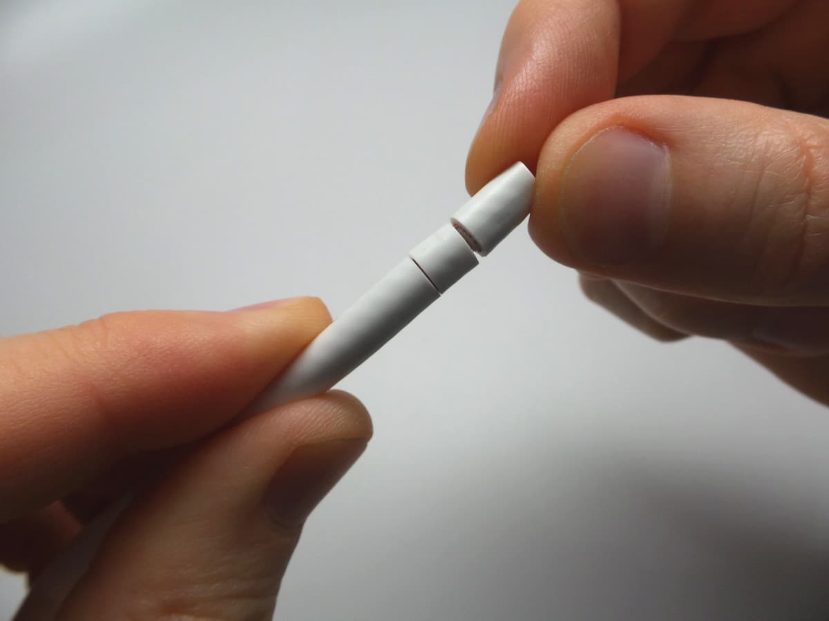
BNC Twist-on Connector

BNC twist-on connectorTwist-on BNC connectors are very convenient because they do not require any special tools to attach the connector to the coax cable. Of course a coax cable stripper is still needed to strip the cable before attaching, but after that everything is done by hand. Despite some installers claiming that BNC twist-on connectors are not reliable because they do not attach as securely as crimp-on or compression connectors, I have found them to be very reliable as long as the cable is trimmed to the proper length according to the twist-on connector that you are using.

Watch this video to see how easy these are to attach.


BNC Compression Connector

F Compression BNC Connector
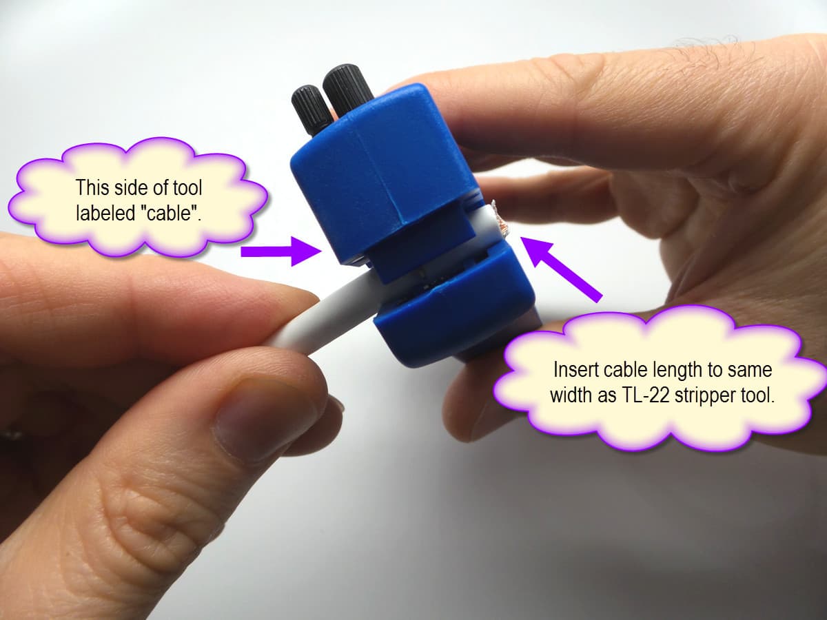
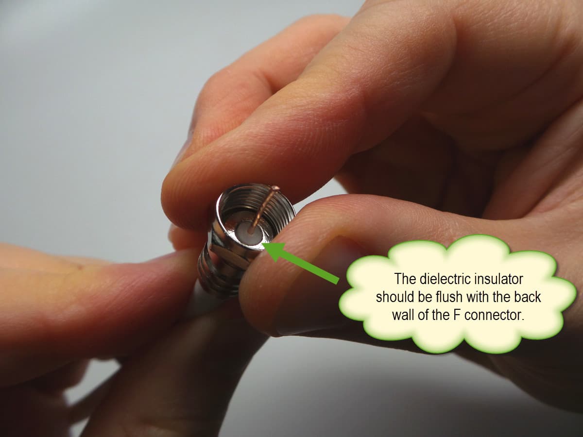
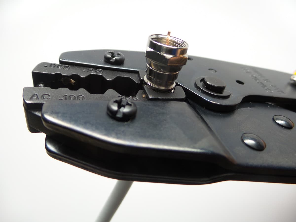
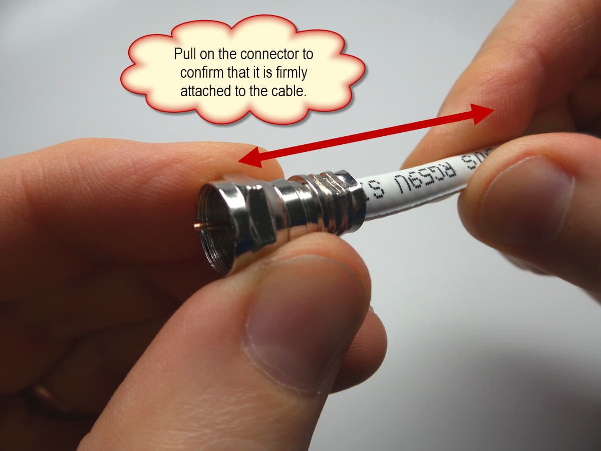
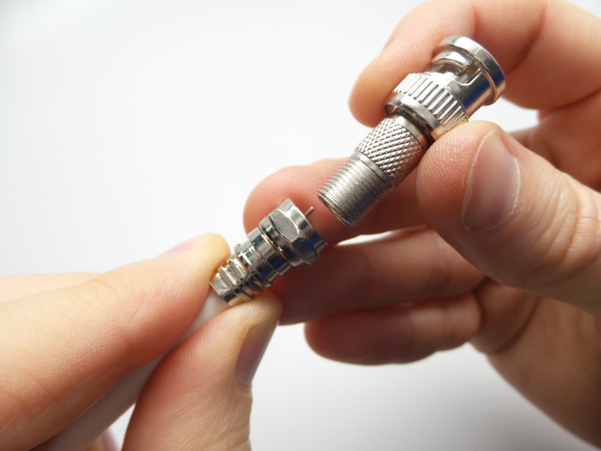
There are two popular methods for attaching compression BNC connectors. One piece BNC compression connectors exist (which is one method), however, many installers prefer to attach a compression F connector to coax cable first, then screw on a BNC connector to the F-connector. The reason that many installers prefer this method is because there is no guessing the correct length of the coax core when you attach F connectors (because the coax core is visible and can be trimmed after). With BNC compression connectors, the core of the coax is hidden when you compress the fitting onto the cable. This can be prone to error.

The other reason that this is a favorite method among profession installers is because many CCTV installers also perform cable TV installations. Cable TV uses the same RG59 and RG6 coax cable that CCTV cameras use. These installers have been attaching F-connectors using a compression tool for years – they are very good at it. It is simple for them to attach a BNC screw on connector to an F-connector.

There is one downside to this method. when you combine the length of the F and BNC connector, it is longer than a twist-on connector. In some cases, installers have a limited amount of space and need the coax to bend away from the camera shortly after the connection is made. This longer connector method, can make working in tight spaces a challenge.

The below video demonstrates this method of attaching a compression F-connector to RG59 cable, then screwing on a BNC male.


Which is BNC Connector is Best?

There is a reason that different types of choices to exist and there is no one size fits all answer here. My opinion is this: before creating the three videos that appear in this article and spending sufficient time practicing with each type of connector, I was convinced that BNC twist-on connectors were not a good choice. However, after taking the time to understand how important getting the length of the cuts just right is and also realizing that the TL-22 coax stripper tool makes the cuts exactly where you need, I really like BNC twist-ons. When cut correctly, I found them to be very secure.

Nothing really beats how secure a compression connector is when attached to coax, and I really like the way that the core of the coax is exposed on the f connector. There is very little guessing when you use this method. Compression tools are not cheap, but they are worth it. If you have the room for the extra length of these two connectors combined, this is probably my favorite.

I should mention that I do not have anything really bad to say about using BNC crimp-on connectors, but I prefer the other two methods after testing all three.

One factor in making a decision in which BNC connector is best for you is the time it takes to attach. If you are really comfortable with a certain type and you are efficient at attaching that type, go with it. After all, the last thing you want to spend a lot of time on is attaching BNC connectors to cable.


Looking for a supplier?

RG59 Cable and BNC Connector Installation Kit

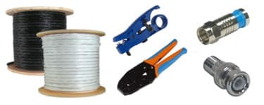
If you are looking for a supplier for connectors, cables, and tools, please take a look at the CCTV cable installation kits that my company offers. We have RG59 kits that include your choice of all three connector types reviewed in this article as well as the tools that you need. If you have any questions, please do not hesitate to contact me at mike@cctvcamerapros.net.


How to Send Push Notifications from Raspberry Pi

$
0
0

Send Push Notifications from Raspberry Pi

This project demonstrates how to send push notifications from Raspberry Pi to iOS and Android devices using a free push app. The idea is to trigger the event of sending the push message with a magnetic door sensor. When the door opens, the Raspberry Pi sends the message. The magnetic door sensor can easily be replaced in this project with some other type of alarm device such as a PIR motion sensor, infrared trip wire, or other.

Disclosure: I am not a Python coding expert or an expert on Raspberry Pi (yet). Although, I have a lot of software engineering experience and I was once a full time developer, this is my very first Raspberry Pi project and Python application. So, it is likely that the Python code is not the cleanest and there may be better ways to setup the Raspberry Pi. I am certainly open to constructive criticism and suggestions. Please post any comments at the bottom of this blog post if you have any.

 Setup Raspberry Pi to Send Push Messages

Here are the things that need to be done.

  1. Setup Push Service at Instapush & Install Mobile App
  2. Wire Door Sensor to Raspberry Pi
  3. Install Python Code
  4. Run Python App
  5. Test and Get the Push Notification

Setup Instapush Account & Install app

To handle the push notifications, I used a free push service called Instapush. Instapush has free apps for iOS and Android and the platform also has a simple to use REST API for software developers.

  1. Sign up for an account here: https://instapush.im/ and login.
  2. Download the apps here:
    iOS App
    Android App
  3. Login to the app(s) using the same login that you created on the website.
  4. After you login to to the mobile app on one or more devices, you will see your device linked to your Instapush account in the control panel. Go here: https://instapush.im/dashboard.
  5. Then click on the devices tab. I have two devices linked to me account. Here is what it looks like.
    mobile push devices
  6. Next, click on the apps tab, then Add Application.
  7. Choose a name for your application then click Add. I named my “Door Push”.
  8. After you add your application, you will brought to the events screen. Click Add Events.
  9. Choose a title for your event. I recommend not using any spaces in the event name. I used “DoorAlert”.
  10. You need to add at least one tracker. This is basically a variable that is used in the push notification. I used {message}.
  11. Last, type what you want your push message to say. My Python code passes the {message} variable to the Instapush service so I recommend that you just add {message} to the Message field with nothing else.
    push notification api
  12. Click Add Event.
  13. Click on the Basic Info tab and make note of the Application ID and Application Secret fields. You will need these in the python code. You can see what this looks like below. I blocked out my ID and key.
    push service key

Wire Door Sensor to Raspberry Pi

I am using a breadboard kit to make it easier to wire the door sensor to Pi. I use GPIO pin 23 and a ground pin to wire the door sensor. It does not matter which lead goes to the GPIO and which goes to the ground. Here is what the wiring looks like.

Raspberry Pi magnetic door sensor wiring

Python Code

Here is the python application that I wrote. The comments in the code should explain pretty well what is going on. Name your program doorSensor.py. I am pretty sure that the formatting of the code will be messed up when I paste it into this blog post, so you can download the Python source here.

# ------------- Begin doorSensor.py ------------------ #
import pycurl, json
from StringIO import StringIO
import RPi.GPIO as GPIO

#setup GPIO using Broadcom SOC channel numbering
GPIO.setmode(GPIO.BCM)

# set to pull-up (normally closed position)
GPIO.setup(23, GPIO.IN, pull_up_down=GPIO.PUD_UP)

#setup InstaPush variables

# set this to Application ID from Instapush
appID = ""

# set this to the Application Secret from Instapush
appSecret = ""

# leave this set to DoorAlert unless you named your event something different in Instapush
pushEvent = "DoorAlert"

# set this to what you want the push message to say
pushMessage = "Door Opened!"

# use StringIO to capture the response from our push API call
buffer = StringIO()

# use Curl to post to the Instapush API
c = pycurl.Curl()

# set Instapush API URL
c.setopt(c.URL, 'https://api.instapush.im/v1/post')

# setup custom headers for authentication variables and content type
c.setopt(c.HTTPHEADER, ['x-instapush-appid: ' + appID,
'x-instapush-appsecret: ' + appSecret,
'Content-Type: application/json'])

# create a dictionary structure for the JSON data to post to Instapush
json_fields = {}

# setup JSON values
json_fields['event']=pushEvent
json_fields['trackers'] = {}
json_fields['trackers']['message']=pushMessage

postfields = json.dumps(json_fields)

# make sure to send the JSON with post
c.setopt(c.POSTFIELDS, postfields)

# set this so we can capture the resposne in our buffer
c.setopt(c.WRITEFUNCTION, buffer.write)

# uncomment to see the post that is sent
#c.setopt(c.VERBOSE, True)

# setup an indefinite loop that looks for the door to be opened / closed
while True:

# door open detected
GPIO.wait_for_edge(23, GPIO.RISING)
print("Door Opened!\n")

# in the door is opened, send the push request
c.perform()

# capture the response from the server
body= buffer.getvalue()

# print the response
print(body)

# reset the buffer
buffer.truncate(0)
buffer.seek(0)

# door closed detected
GPIO.wait_for_edge(23, GPIO.FALLING)
print("Door Closed!\n")

# cleanup
c.close()
GPIO.cleanup()

# -------------------- End doorSensor.py -------------------- #

Save the Python script on your Raspberry Pi.

Start Python App

To test the push notification from Pi, run the doorSensor.py application. While the app is running. separate the magnetic door sensors from each other. You will see the following printed on the screen of your Raspberry Pi. The first line is the command to start the program. The second line is printed when we open the door. Immediately following is a printout of the response received from the push API service. Last, we print when the door is closed.

pi@raspberrypi ~ $ sudo python doorSensor.py

Door Opened!

{“msg”:”Notification Sent Successfully”,”error”:false,”status”:200}

Door Closed!

Get Push Notification

A second or two after you open the door sensor, you should receive the push notification on your iOS or Android app. Here is what the push message looks like when I received it on my Samsung Galaxy. It works just as awesome on my iPhone.

Raspberry Pi push message

CCTV DVR Push Notifications using Raspberry Pi

$
0
0

CCTV DVR Push Notifications using Raspberry Pi

This goal of this article is to document how to enable mobile push notifications on any CCTV DVR using Raspberry Pi. The problem that this project aims to solves is this: many surveillance DVRs that are currently installed around the world were manufactured before the invention of push notifications for iOS and Android mobile devices. In addition, there are still many CCTV manufacturers that have not yet developed push notifications even if they have mobile apps that enable access their DVRs. CCTV Camera Pros speaks to many customers around the world that want to enable push alerts, but do not want to replace their existing DVR. This can be done by adding a Raspberry Pi to your security system and using the source code that I will provide that integrates with a free push notification service from Instapush.

If you are going to attempt to use this project with your DVR, there is one prerequisite: your DVR MUST have an alarm relay output. Alarm in / alarm out ports are very typical even on older security DVRs. Look on the back of your DVR. If it has alarm inputs and outputs, they will  look something like this. The relay outputs can usually be identified with the labels NO / NC / COM, which stands for normally open, normally closed, and common.

CCTV DVR Alarm Relay Output

Unfortunately, if your DVR does not have these alarm output ports, you will not be able to enable push notifications using this Raspberry Pi project.

Setup DVR Alarm Output to Send Push Messages through Raspberry Pi

This project builds off of the “How to Send Push Notifications with Raspberry Pi” project that I published last week. Actually, the Python code that this project uses is almost identical to that one. I just replace the magnetic door sensor as the trigger for the push message with the alarm output of the DVR. I also added an LED output that turns on when the alarm is triggered, but that part is optional. Some of the steps below will reference that project because the setup is the same.

  1. Setup Push Service at Instapush & Install Mobile App
  2. Wire DVR Alarm Relay to Raspberry Pi
  3. Configure DVR Alarm Output
  4. Install Python Code
  5. Run Python Code
  6. Trigger DVR Alarm to Send Push Message

Wire DVR Alarm Relay Output to Raspberry Pi

Here is how my Raspberry Pi is wired for this project. Please note that the LED wired to GPIO 26 is optional. I included it so that I can easily see when the DVR alarm is on.  If you decide that you want to use an LED, you should connect a resistor in-line with the LED. I used a 220Ω resistor. The reduces the power that the LED receives and prolongs its life.

CCTV DVR to Raspberry Pi Wiring

Here is another view of how the alarm relay output and LED are wired to the Raspberry Pi.

Raspberry Pi Alarm Input Wiring

Configure DVR Alarm Relay Output

Different surveillance DVR models support different types of events that can trigger their alarm relay output(s). This part of the project setup is done on your DVR. The iDVR-PRO CCTV DVR supports the following types of alarms. Any of these can be used to trigger the push alert if you are using an iDVR-PRO.

  • Alarm Sensor – you can setup external alarm inputs to trigger an alarm relay output.
  • Video Motion Detection – motion detection from any camera.
  • Video Loss – video being lost on any camera.
  • Disk Drive Alert – disk drive system events such as disk full, failure, overwrite started.
  • Network Event – network events such as remote login failure, Internet connection failure, and DDNS update failure.
  • Panic Recording – initiation of panic recording.
  • System Event – system boot-up warning, login failure, fan failure.
  • Tamper Detection – DVR tampering detected.

So again, the type of event / alarm that you can use will depend on your DVR. This part of the project setup is completely independent of your Raspberry Pi. You should follow the instructions for setting up alarm output on your DVR. Here are the alarm setup instructions for the iDVR-PRO, which you may be able to use to improvise if your DVR does not have instructions.

Install Python Code

Here is the python application that I wrote. The comments in the code should explain pretty well what is going on. Name your program dvrPush.py. I am pretty sure that the formatting of the code will be messed up when I paste it into this blog post, so you can download the Python source here.

Be sure to enter your Instapush application ID and secret in those variable values in the code.

# ------------- Begin doorSensor.py ------------------ #
import pycurl, json
from StringIO import StringIO
import RPi.GPIO as GPIO

# LED Setup
ALARM_IN = 23
LED = 26 # removed this line if you do not setup the LED

#setup GPIO using Broadcom SOC channel numbering
GPIO.setmode(GPIO.BCM)

# set to pull-up (normally closed position)
GPIO.setup(ALARM_IN, GPIO.IN, pull_up_down=GPIO.PUD_UP)
GPIO.setup(LED, GPIO.OUT) # removed this line if you do not setup the LED
GPIO.output(LED, False) # removed this line if you do not setup the LED

#setup InstaPush variables
appID = “” # add Instapush application ID here
appSecret = “” # add Instapush application secret here
pushEvent = “DoorAlert”
pushMessage = “Door Opened!”

# use this to capture the response from our push API call
buffer = StringIO()

# use Curl to post to the Instapush API
c = pycurl.Curl()

# set API URL
c.setopt(c.URL, ‘https://api.instapush.im/v1/post’)

#setup custom headers for authentication variables and content type
c.setopt(c.HTTPHEADER, ['x-instapush-appid: ' + appID,
'x-instapush-appsecret: ' + appSecret,
'Content-Type: application/json'])

# create a dict structure for the JSON data to post
json_fields = {}

# setup JSON values
json_fields['event']=pushEvent
json_fields['trackers'] = {}
json_fields['trackers']['message']=pushMessage
#print(json_fields)
postfields = json.dumps(json_fields)

# make sure to send the JSON with post
c.setopt(c.POSTFIELDS, postfields)

# set this so we can capture the resposne in our buffer
c.setopt(c.WRITEFUNCTION, buffer.write)

# uncomment to see the post sent
#c.setopt(c.VERBOSE, True)

# setup an indefinite loop that looks for the door to be opened / closed
while True:

# DVR Alarm received
GPIO.wait_for_edge(ALARM_IN, GPIO.RISING)
GPIO.output(LED, True) # removed this line if you do not setup the LED
print(“DVR Alarm Started!\n”)

# send the push request to Instapush
c.perform()

# capture the response from the Instapush server
body= buffer.getvalue()

# print the response from the Instapush API call
print(body)

# reset the response buffer
buffer.truncate(0)
buffer.seek(0)

# DVR alarm has stopped
GPIO.wait_for_edge(ALARM_IN, GPIO.FALLING)
GPIO.output(LED, False) # removed this line if you do not setup the LED
print(“DVR Alarm Ended.\n”)

# cleanup
c.close()
GPIO.cleanup()

# ——————– End doorSensor.py ——————– #

Save the Python script on your Raspberry Pi.

Run Python Code

To test the push notification, run the dvrPush.py application. While the app is running. Trigger the alarm output on your DVR. How you do this will depend on the type of event you configured on your DVR to trigger the relay. You will see the following printed on the screen of your Raspberry Pi when the alarm is sent from the DVR to Rpi. The first line is the command to start the program. The second line is printed when the DVR triggers the relay output. Immediately following is a printout of the response received from the push API service. Last, we print when the event on the DVR has ended and the relay is opened.

pi@raspberrypi ~ $ sudo python dvrPush.py

Door Opened!

{“msg”:”Notification Sent Successfully”,”error”:false,”status”:200}

Door Closed!

Send Push Notification

A second or two after you trigger the DVR alarm, you should receive the push notification on your iOS or Android app. Here is what the push message looks like on an Android Samsung Galaxy. It works just as awesome on iOS.

Raspberry Pi push message

Send Security Camera Photos from Raspberry Pi via MMS Text Message

$
0
0

Raspberry Pi Send Photo to Mobile via MMS Message

This project demonstrates how to setup Raspberry Pi as a security camera system that can take a photo snapshot send the image to mobile phones using MMS text messages. The action is triggered by an GPIO alarm input. I use a magnetic door sensor to trigger the alarm in the Python application that I wrote, but any type of sensor or event can be setup to trigger the Raspberry PI to take the snapshot and send the message. I use a service called Twilio to send the MMS text messages because they have a simple Python SDK for programmers and the service is free to use when in trial mode.

Setup Raspberry Security Camera System

Here are the things that need to be done to setup this project.

  1. Setup Twilio Account
  2. Install Apache Web Server
  3. Install Python Code
  4. Install Pi Camera & Wire Door Sensor
  5. Setup Static IP address
  6. Setup Port Forwarding
  7. Setup Dynamic DNS (optional)
  8. Run Code / Get MMS Message
  9. Run Alarm Code On Boot

Update 11/6/2014: Alternative use of imgur API instead of running a web server on Raspberry Pi

After launching this project, I received some great feedback on Reddit. /u/kurashu89 made a suggestion to use the imgur API instead of hosting the image on an Apache web server instance. Doing this has the following benefits.

  1. There is no need to setup a web server and use additional memory resources on RPi
  2. No need for the RPi to have a static LAN IP address
  3. No need for port forwarding
  4. No need to worry about DDNS

The one additional step that is required if you would like to use imgur for the snapshots is that you need to setup a imgur account and register a developer application. So, if you decide to use this method, you can skip steps 2, 5, 6, and 7 above and you need to install the alternative imgur source code provided here.

Setup Twilio Account

Twilio makes sending SMS / MMS messages simple by managing the connections with all of the different mobile providers for you. Software developers can use a simple Python API / SDK to request that a message be sent and the Twilio service takes care of the rest. To enable a trial account, Twilio requires two things. 1) You need to verify the phone number that you wish to send messages to and 2) the Twilio service prepends “Sent from a Twilio Trial account” to trial account messages. As far as I can tell, the service is free to use as long as you are sending 250 messages or less per month.

  1. Signup for a free Twilio account here.
  2. As part of the signup process, you need to verify a phone number. Use the cell phone number that you want to send messages to.
  3. After you verify your phone number, Twilio will assign you an account phone number to use that is in the same area code as the number you verified. This is the phone number that will be sending MMS messages on your behalf.
  4. Click get started, then Go to Your Account.
  5. When you login to your account, you will see an Account SID and Auth Token field at the top of the screen. Click on the lock icon in front of the Auth Token field to reveal the value. Make note of these two values. You will need them for the Python code shortly.
    MMS Message Account
  6. Just below these fields you should also see your Twilio phone number. You will need this also when you configure the RPi camera application.

Install Apache Web Server

You are probably wondering why you need to install the Apache web server on your Raspberry Pi for this project. Here is the answer: in order for the Twilio service to send a photo with MMS messages, it needs to get the photo from a URL on the Internet. The Twilio SDK will retrieve the photo taken by your Raspberry Pi camera via a URL served by the Apache web server running on your RPi.

  1. If you do not already have Apache running on your Raspberry Pi, click here to follow these instructions on the RaspberryPi.org website.
  2. The default installation of Apache makes /var/www/ the DocumentRoot which means that is where the web server looks for files to serve. My Python application assumes that you are using the default “/var/www” DocumentRoot, but if you are not that is OK, you will just need to modify the APACHE_DOC_ROOT variable in the code.

Install Python Code

Before you install the Python script, you must install the Twilio SDK on your Raspberry Pi. Download the Twilio Python SDK here. There are several ways that you can install it that are documented on that page.

Apache Method

Here is the Apache based Python application that I wrote to create the security camera system. The comments in the code should explain what is going on pretty well. You will only need to modify the CONSTANT variables that are defined at the top part of the app.

You can download the source code here.

Imgur Method

This is the version of the system that uses Imgur instead of Apache (I know, I should merge the two into one code base). I will likely so that later.

You can download the Imgur based source code here.

  1. Download the source code to your Raspberry Pi. If your RPi is already connected to the Internet, use the following command to get the source code.
    wget http://videos.cctvcamerapros.com/downloads/python/mms-alarm.py
  2. Edit the mms-alarm.py application using the editor of your choice on your Raspberry Pi.
  3. Change these variable values in the code.
  4. SENSOR: you can leave this value set to 19 if you are going to use GPIO 19, otherwise change as needed.
  5. DELAY: this is set to zero, but if you want a delay time between the alarm sensor being triggered and the camera taking a picture, change this to the number of seconds of delay that you require.
  6. ACCOUNT_SID: put the value from your Twilio account here.
  7. AUTH_TOKEN: put the value from your Twilio account here.
  8. TO_PHONE: this must be set to the phone number that you want your Raspberry Pi to send the MMS message to. This must be the phone number that you already verified during the Twilio account setup.
  9. FROM_PHONE: this must be set to the phone number that Twilio assigned to you during the account setup process.
  10. TXT_MSG: this is the text message that you want to be sent along with the photo that your RPi will take.
  11. CLIENT_ID: (ONLY for imgur code) this is the imgur Client ID assigned to the app you registered.
  12. HOSTNAME (not used if using imgur): set this to the public IP address (or the DDNS hostname) of your Raspberry Pi and the port number that you will use for forwarding. This WILL NOT work using a LAN IP address because the Twilio service will be accessing your Raspberry Pi from remotely over the Internet. IP addresses begining with 192. or 10. WILL NOT work. This is explained further in the port forwarding and DDNS sections of this project.
  13. APACHE_DOC_ROOT (not used if using imgur): if you installed your Apache web server with the default DocumentRoot, you do not need to change this value.
  14. IMG_DIR (ONLY for imgur code): location where you want the snapshot saved on your RPi.
  15. IMG: this is the name of the photo that will be saved. There is no need to change this unless you do not want the image to be named snap.jpg. This image will be overwritten each time the alarm is triggered.
  16. IMG_WIDTH: I have the image size set to 800 x 600 by default. I do not have any need to send a high resolution image over text, but if you do, you can change it here.
  17. IMG_HEIGHT: see explanation above.
  18. Save the file after you have changed these values.

Install Camera & Door Sensor

I am not going to document how to install a Raspberry Pi camera in this project because there are plenty of articles and videos available online that can show you how to do that. Just search Google for “install raspberry pi camera” if you have not yet installed yours.

The door sensor wiring is very simple. You can use any magnetic door sensor. I am using a Honeywell. Wire one of the terminals of the sensor to GPIO pin 19 of your Raspberry Pi or any other GPIO of your choice. The mms-alarm.py code that I provide is setup for GPIO 19, so if you use a different pin, make sure you update the SENSOR variable. Wire the other sensor terminal to a ground (GND) port of your Pi. you can see my wiring below. I am using a breadboard which is totally overkill for such a simple project, but I still like using it.

wire raspberry pi door sensor

Setup Static LAN IP Address (DHCP Reservation)

If you want to save a lot of time and frustration, you should set a static LAN IP address for your Raspberry Pi. I recommend doing this by reserving an IP address in your router. I find this method to be most reliable and most routers have an IP reservation function. The process to do this will depend on your specific router type. Here are instructions for a D-Link router. The concepts are the same for any make and model of router but the interface will be different. Do a search online for your specific model. Search for “LinkSys IP reservation” or “Linksys DHCP reservation”. Obviously replace Linksys with your manufacturer and model.

Setup Port Forwarding

When the Python application calls the Twilio MMS service, one of the parameters that is passed to Twilio is the URL on your Raspberry Pi where the image to send with the message is located. Because the Twilio service will be accessing this URL from remotely over the Internet, it is necessary to setup port forwarding to the Apache web server running on your RPi.
Just like the DHCP reservation setup above, the concept of port forwarding is the same but the setup process is different depending on your specific router.

By default, Apache web servers run on port 80. Please watch the below video if you want to understand port forwarding better. In concept, replace the IP camera used in the video with your Raspberry Pi and the computer on the left of the network diagram in the video with the Twilio service and you should understand how port forwarding will be working for this project.

You can find port forwarding instructions here for many popular manufacturers. Do a Google search for your specific make and model if you can not find yours there.

Dynamic DNS Setup (DDNS)

If the Internet connection where your Raspberry Pi is located does not have a static IP address, you should setup a Dynamic DNS account (DDNS). You can find an explanation of DDNS and setup instructions for some routers here. If you do end up setting up DDNS, then be sure to use your DDNS hostname in the HOSTNAME variable of the mms-alarm.py application. If your internet connection uses a static IP, then it is not necessary to setup DDNS and you can simply use the IP address of your Internet gateway in the HOSTNAME variable.

If you need to find your Internet IP address and if you would like to test to make sure that you have port forwarding setup correctly, please use this online port forward checker tool. The tool also displays your Internet IP address.

Run Alarm Code / Get MMS Message

You can test the project by starting the Python application manually. After you confirm that it works correctly, you may want to automatically startup the Python application when your Raspberry Pi boots up.

To start the app manually, change directory to where it is located and type the following command:
sudo python mms-alarm.py

When your door is opened (alarm sensor separated), the following will be printed on the screen: Door Opened!

Within a few seconds, you will receive the MMS message with the photo attached that your Pi camera captured. Mine looks like this.

Raspberry Pi Send MMS Message with Photo

Startup Alarm Application on Boot

If you decide to use this project in real life, you will most likely want the alarm code to startup when your Raspberry Pi boots up. To start the program on boot, you can add a startup command to the rc.local file on you RPi. This file will either be located in /etc or /etc/rc.d

Change directory to /etc to see if your rc.local is located there. If it is not, change directory to /etc/rc.d.

Edit the rc.local file using the text editor of your choice and add the following line before the last line in that file which should read “exit 0″
python /home/pi/alarm.py &

Save the file, then reboot your Raspberry Pi and test the alarm application again by opening your door.

That is all. If you have any questions, you can email me at mike@cctvcamerapros.net.

Create a Time Lapse Movie with an IP Security Camera and Free Video Software

$
0
0

time lapse video ip security camera free software
This article explains how to use a IP security camera and free open source video editing software to create a time-lapse movie. Please note that this process is not completely automated and does require some manual processing, but not much. Also, if you are going to do this project, I assume that you have a network IP camera that is capable of capturing snapshot images at an interval that you can configure.

As an alternative to IP cameras, you can use a CCTV camera with a network video server. Again though, the video server must support still image captures.

I will use mencoder on a Windows PC to encode the video. Please note that mencoder can be run on other operating systems and the process will be almost identical to this, but in this article I specifically use a Windows computer to document the process.

Configure IP Camera to Capture Images

Time lapse photography is something that I have experimented with and written about in the past. Please reference this article that I wrote in 2012 to see how to configure a Zavio IP camera to take timed snapshots.  You can see the video that was created from that project here. At that time, I used commercial software to create the time -lapse movie of the snapshots that I captured of my ant farm. I saved all of the images from that original project and I will reuse them here.

If you are not using a Zavio camera for your project, you should check the documentation of your IP camera to see if it supports taking interval based snapshot photos. I think that most IP cameras that have an on board SD card support this function.

If you are going to use a CCTV camera, this Zavio video server can be configured in the same way as a Zavio camera to take snapshots.

Download Pictures

After you have captured the images for the duration that you choose, download the images from your IP camera to your PC. The images will most likely be JPEG type. Save them all into a single directory and remember where you put them. We will come back to that location shortly.

Download Mencoder Software

Mencoder is a free open source software package that supports video decoding, encoding and filtering from the command line. Mencoder is released under the GNU General Public License. Download it here.

Be sure to download either the 32-bit or 64-bit binary version depending on which version of Windows your computer is running. If you are unsure if you are running 32 or 64 bit, right click on Computer and select properties, or select Control Panel > System & Security > Set the name of this Computer. The following screen will display and you can see if your system is 32 or 64 bit.

Windows 32-bit or 64-bit


After you download the zipped mencoder file, unzip it. It will be unzipped into a folder that is named something like “mplayer-svn-37324-2-x86_64″.  Rename that folder “Mencoder” and move the Mencoder folder into the C:\Program Files directory. So, the new location will be C:\Program Files\Mencoder

Create Time-Lapse Movie using Mencoder

Remember the location of your snapshot images? I hope so. We need to go there now.

Open up a command line window. You can do this by selecting Start then typing the following in the “search programs and files” field: cmd. Press enter or click on the cmd program that the search finds. A command line shell will open. Change directory to the location of your snapshot images. I put mine in C:\Users\admin\Downloads\Time-Lapse Pics.

Once you are your snapshots directory run the following command. Please note that you may want to change a few of the options of this command. My snapshots were captured at 720p resolution so I set the video scale to 1280:720 so that it matches the original size of my photos. You can change this to match yours or scale it down to the video size that you want.

I set the frame rate of my movie to 12 frames per second. This is set by setting fps=12. You can change this as you see fit. You probably want to experiment with the framerate to get the right effect for your time-lapse. Make a video with the frames per second set to 1 or 2, then again with it set to 12 and you will see what I mean. I compare 2 FPS to 12 FPS below.

Here is the command that you run to create the video.

\Program Files\Mencoder\mencoder “mf://*.jpg” -mf fps=12:type=jpg -ovc lavc -lavcopts vcodec=mpeg4:mbd=2:trell:vbitrate=3000 -vf scale=1280:720 -oac copy -o movie.avi

Here is a screenshot of my session from the command line.

mencoder create time-lapse video

Time Lapse Videos

I originally captured 1600 images over the course of 4 days for my movie. I encoded the video twice, then uploaded them to YouTube. On the first video the frame rate is set to 12 FPS. On the second, I lowered it to 2. Watch both videos below to see the difference. Note: if you are going to play both videos at the same time, you should turn off the audio. The mix of the two songs is not good.

12 FPS Time-Lapse

2 FPS Time-Lapse


That is it. If you follow these steps, you should be good to go. If not or if you have questions, please let me know. Thanks for checking out my article!

CCTV Camera with PIR Motion Detector Light and Alarm Relays

$
0
0

CCTV camera with PIR Motion Sensor Light and Alarm Relay

The PIR-BL7 is a CCTV camera with PIR motion detector lights and alarm relay input and outputs.

A few months ago, I began testing the PIR-BL7 CCTV camera. I am always excited to test out a new product that has some unique feature or ability that make it special. This camera has several features that make it very special.

  1. Built in PIR motion sensor
  2. 30 white LEDs make up a security light
  3. Alarm relay output / Alarm inputs

Surveillance Camera with Alarm Relay PIR Sensor

PIR Motion Sensor

The PIR motion sensor is located on the front of the camera, just below the camera lens. This motion sensor is designed to detect movement of human sized objects when they come into view of the camera’s lens. The camera has a 2.8-12mm varifocal lens which when adjusted to the widest angle (the 2.8mm setting) the camera provides a 109 degree horizontal field of view. The PIR sensor detects motion across a 100 degree field of view. Please note that if you adjust the lens to a more narrow field of view, this does not effect the area where the PIR sensor will detect motion.

In my experience, using a PIR sensor based motion detection is much more reliable than software based video motion detection (especially for outdoor video surveillance). Typically there are a lot of small moving objects outdoors which makes it difficult to get the sensitivity just right. When security cameras turn to night mode, there is typically some video noise because of the lack of light. This noise can cause false alarms when using video motion detection. A PIR sensor uses infrared light to measure the radiation reflected by objects in its view. When a certain amount of this radiation changes, the PIR sensor triggers an alarm, so they are not susceptible to some of the challenges of outdoor video motion detection.

LED Security Light

The 30 white LEDs on the front of the camera make up the “security light”. Instead of using infrared LEDs and capturing black and white video during night time operations, this security camera can always record in color. When in night mode, the white LEDs turn on when motion is detected by the PIR sensor. Being that the area is illuminated by the LEDs whenever there is movement, the camera always records in color.

When the LEDs are off, the camera uses Sense-up light intensifier technology which makes it able to capture color video even in very low light environments. Watch this video to see how well this camera works, even with the lights off. I use my iPhone to show just how dark the room is where I am testing.

Alarm Relay Output / Alarm Input

The PIR-BL7 would be a great camera if the motion detector lighting was the only special feature that it had, but the camera also has built in alarm relay inputs and outputs that make it a truly outstanding security camera in my opinion. Here is how the alarm inputs and outputs work.

In addition to the power and video lead, there is a third cable lead connected to the camera that contains a block of wire terminals. These give the installer access to the alarm relays.

CCTV Camera Alarm Relay

Alarm Relay Output

The alarm relay output can be connected to just about any low voltage alarm component that uses it’s own low voltage power supply such as a external strobe light or audio siren. When motion is detected by the PIR sensor, the alarm relay out is closed / activated which will turn on the device that is connected to the relay. Please note that the alarm relay output is limited to devices that use a max voltage and current of  30V DC 2 Amp.

CCTV camera alarm relay output


The alarm relay output is also activated when the alarm relay input is triggered.

Alarm Input

The alarm input can be used to connect sensors such as magnetic door sensors. When the door sensor is opened,  the alarm relay output and digital alarm output is triggered.

CCTV camera alarm input


Digital Alarm Out

The digital alarm out is used to send a 5v DC signal to devices such as DVRs. You can see how this can be used to trigger alarm recording on a DVR here.

CCTV  camera digital alarm out


The digital output of the camera is triggered when either of these events occur: 1) The PIR sensor detects motion 2) The alarm relay input is activated.

Please note: although the PIR sensor only turns the LED lights on at night, it triggers the alarm relay output and digital alarm output in day and night.

Summary

I installed two PIR-BL7 cameras at my house a few months before we started selling them. I personally test all of the CCTV cameras that we supply and I like to leave them running in a real production environment to make sure that they perform well. When my testing is done, I take them down to make room for the next test. I ended up liking the PIR-BL7 so much that I am keeping the two that I tested at my house permanently as part of my personal home surveillance system.

Here is the one that I have mounted just above the garage door. I have the camera lens set to the widest position and it provides great coverage of the entire 3 car wide driveway. The streetlights provide enough lighting for this camera such that the LEDs are not even really needed for this area, but the 24/7 color video is so nice, I just left it there.

cctv-camera-garage-installation-wide cctv-camera-garage-installation-2 cctv-camera-garage-installation home-video-surveillance-installation-4

I have the other PIR-BL7 mounted at the front door entryway to my home. This is an area that does not get much light at all, especially being that the light at the entryway does not work. Unless there is moonlight, this location is pitch black. If anyone approaches the door after dark, the PIR sensor picks them up and the LEDs turn on before they get to the door. This illuminates the entire entryway very well.

surveillance-camera-home-front-door cctv-camera-home-front-door motion-sensor-light-camera security-camera-home-front-door

Here is a video that I captured from the PIR-BL7 that is connected to my iDVR-PRO8A. I exported the video from the DVR and uploaded the MPEG4 video to YouTube. Please note that there is zero light in this entryway. That is why it is so dark before the LEDs turn on. Please also note that the video gets degraded slightly when re-encoded for YouTube.

If you would like more information and current pricing for the PIR-BL7, please visit this page.

Raspberry Pi Twitter Project: Push Button, Camera Capture, Tweet Photo

$
0
0

Raspberry Pi Twitter

In this project, I program my Raspberry Pi (using Python) to take a picture using a Pi camera, then share the photo via Twitter when a button is pressed. I use the Twython python library to integrate with the Twitter API. I realize that I am not the first person to document a Twitter project like this, but I chose to share my own version for a few reasons.

1) I kept getting the following warning from the Twython library when using the update_status_with_media() method.
“TwythonDeprecationWarning: This method is deprecated. You should use Twython.upload_media instead.”

All of the projects that I found online used that deprecated method to tweet a photo. After a bit of research, I found the new method of photo sharing via the Twitter API requires that you make two API calls. One to upload the media file and the second to tweet using the reference the ID of the media file. The Python code for this project gets rid of that warning.

2) I really like to use the GPIO ports on Raspberry Pi when I can.  I have been designing and developing software for many years but I am still a noob when it comes to electrical circuitry design. So, I wanted to use a push button to trigger the tweet and use LEDs to report the status of the process. Not the most intricate of wiring projects, but every bit of experience helps.

3) I tested this entire process on a brand new install of the Raspbian os for Raspberry Pi. I wanted to provide step by step instructions using a fresh install so that I can document any library dependency that I may run into.

Project Setup Steps

Follow these steps to configure and program your Raspberry Pi to take a photo and share it via Twitter when you push a button.

  1. Add Mobile Number to Twitter
  2. Setup Twitter App
  3. Install Pi Camera
  4. Install Python Libraries
  5. Install Program Code
  6. Wire Raspberry Pi
  7. Run the Code / Press the Button

Add Mobile Phone Number to Twitter

To interface with the Twitter API / SDK, you must setup a Twitter app that has both read and write access to your timeline. In order to do this, you must have a Twitter account with a verified mobile phone number associated with it. After you create the app, you can remove your mobile number. I assume that you already have a Twitter account, but if you do not, please create on here.

  1. Login to your Twitter account.
  2. Click on your Twitter icon in the upper left and select Settings.
    twitter raspberry pi project
  3. After you are logged in, click on the Mobile link on the left.
    twitter python phone number
  4. Add your mobile phone number and click Continue.
  5. A verification code will be send to you. Enter that code on the confirmation screen.

Setup Twitter App

  1. From the same web browser where you are logged  into your twitter account, go to https://apps.twitter.com/
  2. Click on Create New App.
  3. Fill in Name, Description, and Website. Agree to T&Cs. Click Create your Twitter application button. Do not worry if you don’t have a website for the project, just fill this in with any valid web address. Be sure to include the “http://”.
    twitter raspberry pi python project
  4. Click on Permissions Tab. Select Read and Write. Press Update settings.
    raspberry pi twitter setup
  5. Click on the Keys and Access Tokens tab, then click on the Create my access token button.
    twitter app setup keys
  6. After you press the Create my access token button, you will see the Access Token and Access Token Secret fields. Keep all of these field values handy. You will need them for the Python code.
    Consumer Key (API Key)
    Consumer Secret (API Secret)
    Access Token
    Access Token Secret

Install Pi Camera

If you do not already have a Pi camera connected to your Raspberry Pi board and enabled, please follow the instructions here to get that done. If you prefer to use a USB web cam, you can find instructions to set that up here. If you are a noob, I recommend using a native Pi camera because my project code is already setup to use one.

Install Python Libraries

Use the below commands to install the required Python libraries. The only one required for this project is twython.

In case you do not already have pip installed, I included commands to install that first. Remember, I am testing this from a fresh Raspbian build. If you already use pip to install Python libraries, you can skip steps 1 and 2.

  1. sudo apt-get update
  2. sudo apt-get install python-pip
  3. sudo pip install twython

Install Program Code

Here is the source code for the project. The comments explain what is going on.

You can download the source code here if you do not want to use wget to retrieve it.

  1. I recommend creating a new directory for any project. You can use this command to create a new directory.
    mkdir tweet
  2. Change into that directory using this command.
    cd tweet
  3. You can use the following command on your Raspberry Pi to retrieve the source code for this project. It will be placed in the tweet directory as long you are there when you run it.
    wget http://videos.cctvcamerapros.com/downloads/python/rpi-tweet-pic.py
  4. Edit the rpi-tweet-pic.py using your favorite text editor. I use vi.
  5. Look for the variables: apiKey, apiSecret, accessToken, and accessTokenSecret and enter the values from the Twitter app that you created.
  6. By default, I have the image size set to 1280 x 720. You can adjust this by editting the IMG_WIDTH and IMG_HEIGHT variables.

Wire Raspberry Pi

Here is how I wired the push button and LEDs to my Raspberry Pi board. Pushing the button is the action that initiates the camera taking a photo, then uploading and sharing the photo via Twitter. The green LED is used to indicate that the system is ready and you can press the button. The red LED indicates that the program is running. I am using resistors with the LEDs and button.

Disclosure: Though I aspire to be one day, I am not an electronics expert at this time. I am much stronger at software system design and development. If you see anything wrong with the way I have wired my board, that will not surprise me.  If you have any suggestions for improvement, please let me know. I used resistor sizes that I saw being used in other projects using similar hardware.

Also please note that the image below does not reflect the actual GPIO ports that I used in my project code. I use these ports on the diagram because they were spaced out to make it easier to see. You can use any three GPIO ports that  you choose, but please note that if you do not use the ones that I did, you need to modify the following variables in the code.

BUTTON = 12
SYSTEM_READY = 26 # indicates that program is ready to be run
SYSTEM_RUNNING = 13 # indicates that program is running
Raspberry Pi Twitter Project Wiring

Run the Code / Press the Button

It’s time to start the program and push the button to test it out. Here is a terminal session that shows how to do that.

Rasperry Pi Send Tweet

  1. Run this command:
    sudo python rpi-tweet-pic.py
  2. The program will start. When it is ready, the following message will appear and the green LED light will turn on.
    System Ready- push button to take picture and tweet.
  3. When you push the button, the green LED light turns off and the red one turns on which indicates that the program is running.
  4. The program prints out a status at each stage.
  5. When it is complete the following message is displayed, the red LED turns off and the green LED turns back on.
    Done – System ready again.

This is what it looks like on Twitter.

Raspberry Pi Tweet Picture


Not the most exciting tweet. That is the view from my office. My Raspberry Pi and camera are sitting on my desk. That is my brother out there hard at work.

Compare 2 Megapixel vs 5 Megapixel IP Security Camera Resolution

$
0
0

2 megapixel vs 5 megapixel ip camera

Want to compare 2 megapixel to 5 megapixel IP security camera resolution? Here is a quick blog post that contains surveillance snapshot images that we captured at CCTV Camera Pros office to show you the difference. Viewers should click on each image to see the full size view, then zoom in using your browser by clicking on the image again. You will not see any difference until you view the full size images.

2 Megapixel Resolution Image

2 Megapixel IP Security Camera Image

This 2 megapixel image was captured using a Zavio F3210 cube IP camera at 1920 x 1080 resolution. Please click on the image to see the full size or right click on the image and save.

5 Megapixel Resolution Image

5 Megapixel IP Security Camera ImageThis 5 megapixel image was captured using a Zavio D7510 dome IP camera at 2560 x 1920 resolution. Please click on the image to see the full size or right click on the image and save.


How to setup a Raspberry Pi Video Streaming Server in 5 Minutes

$
0
0

Raspberry Pi Video Streaming

Here is a super easy way to setup video streaming on Raspberry Pi so that you can access live video from iOS, Android, Windows, and Mac. The best part is that it actually takes less than 5 minutes to setup.

I have been developing and testing a lot of Raspberry Pi projects lately, especially ones that use the pi camera. I really love having complete control over this tiny Linux computer to do things like create time lapse video, auto sharing photos on twitter, and send push notifications based on alarm events.

My latest project craving was to setup live video on a web page that I could access from the web browser on my iPhone. A quick search on Google revealed many existing projects that already did this. So, I read through some of the more recent ones to try and pick the best one.

I decided to give the instructions in Miguel Grinberg’s Video Streaming with Flask article a try. Miguel’s explanation on his blog was very thorough and his code looked very clean. I was also interested in learning more about Flask (which his app used).

To my delight, I was able to get a live video streaming server running on my Raspberry Pi in under 5 minutes by using the project that Miguel shared on Github.

This is what it looked like from iOS when I was done.

Raspberry Pi Video Streaming

Here is how it is setup. If you do not already have a Pi camera setup, please refer to this page to do that first. By the way, I am using the Raspbian operating system on my RPi.

Raspberry Pi Streaming Video Setup

  1. Install the flask Python library by running this command:
    sudo pip install flask
  2. Download Miguel’s Flask video streaming project by running this command:
    git clone https://github.com/miguelgrinberg/flask-video-streaming.git
  3.  In the project folder edit the app.py file.
    Comment out this line by adding a “#” to the beginning
    #from camera import CameraUn-comment this line
    from camera_pi import Camera
  4. Save the file.
  5. Run this command to find out the local IP address of your Raspberry Pi.
    ifconfig
  6. You will see many lines of output. You are looking for this one:
    inet addr:192.168.0.107 Bcast:192.168.0.255 Mask:255.255.255.0
  7. The inet addr is your local IP address. In this case, 192.168.0.107.
  8.  Start the Flask server by running this command:
    python app.py
  9. You will see this, which means that the server is running on port 5000 and is ready.
    * Running on http://0.0.0.0:5000/
    * Restarting with reloader
  10. Open up a web browser on your favorite device and go to this address http://192.168.0.107:5000, except replace that IP address with the one that your Raspberry Pi is running on.
  11. You should see a live view the video that your Raspberry Pi is capturing.

I hope that this project got you up and running as quickly as it did for me. Please note that I did not get into how to setup port forwarding so that you could access your camera remotely over the Internet. These instructions will only work from a computer that is connected to the same local area network as your Raspberry Pi. You can refer to these notes and instructions from another project if you want to configure your Raspberry Pi for remote access.


How to use Apple TV or Chromecast to View Surveillance Cameras

$
0
0

View Surveillance Cameras with Apple TV or Chromecast

Most surveillance system owners want a convenient way to view the live video from their security cameras on a TV. Apple TV and Google Chromecast provide an convenient wireless alternative to hard wiring a spot monitor output from a DVR. This article will compare using a spot monitor output to mirroring using mobile apps to view video surveillance on a TV.

DVR Spot Monitor Output

The traditional way to setup security camera viewing on a TV (when a DVR is used) is to connect the spot monitor output of the DVR to one of the analog video inputs of the TV monitor. Analog video inputs on TV sets typically use an RCA type input. A coaxial cable is run from the BNC spot output of the DVR to the RCA video input of the TV.

When the user wants to see their cameras, they simply switch the TV to the video input that the spot monitor is connected to. This is a very convenient method for viewing, but sometimes no so convenient to setup because running the coax cable is difficult or not possible at all. Below is a diagram that shows a DVR with multiple spot monitor outputs connected to multiple TVs. You can learn more about spot monitor setup here and you can see a demo video and additional wiring diagrams here.

CCTV Security DVR Spot Monitor


Using Apple TV to View Surveillance Cameras

If your surveillance system includes an iOS app to access your DVR, you can use Apple TV to view your cameras.

View Security Cameras on Apple TV


Here is how it works.

  • The iPhone and Apple TV are connected to the same network via a wireless router.
  • The Apple TV is connected to the TV using an HDMI cable.
  • The video input of the Apple TV is selected using the TV’s remote control.
  • The DVR viewer app is started on the iPhone (or iPad).
  • AirPlay is enabled on the phone in mirror mode.
  • As you navigate the app on your iOS device, everything that you do is mirrored on the TV.

You can find detailed setup instructions on setting up Airplay mirroring here.

Apple TV Demo Video


Watch this video to see Airplay mirroring on Apple TV being used to view security cameras connected to an iDVR CCTV DVR.


Using Google Chromecast to View Surveillance Cameras

If you are an Android user, Google Chromecast provides the same mirroring functionality that Apple TV does using the Chromecast app.

View Security Cameras on TV with Chromecast

Here is how it works.

  • The Android phone and Google Chromecast are connected to the same network via a wireless router.
  • The Chromecast  is connected to the TV using an HDMI cable.
  • The video input of the Chromecast is selected using the TV’s remote control.
  • The DVR viewer app is started on the phone.
  • The Chromecast app is running on the phone and cast screen is enabled.
  • Everything that you do on your Android is now cast (mirrored) on your TV.

You can find detailed information about setting up the cast screen feature of Chromecast here.

Chromecast Demo Video


Watch this video to see Google Chromecast being used to view surveillance cameras connected to an iDVR-PRO CCTV DVR.


Can Apple TV or Chromecast View Cameras Remotely?

A few days after writing this article, I received an email from a reader who asked the following question.

I was wondering if you could make this work if you had CCTV cameras at a vacation lake house and wanted to view the video on TV from a remote location?

Here is the information that I supplied to this reader.

Yes. Because Chromecast or Apple TV is mirroring on your TV whatever is happening on your Android or iOS device, it does not matter if the app is displaying video from cameras that are local to the same network that you are on or if you are accessing a surveillance system from remotely over the Internet. As long as port forwarding is setup properly where your system is located and you can access your cameras from a viewer app, it will work fine.


Summary & Recommendation

If you want to view your security cameras on your TV and are unable to run coaxial cable, Chromecast and Apple TV provide a great alternative traditional hard wired spot monitor installations. The downside is that there are many more steps involved in accessing the video stream on your TV when using these devices. With a hard wired DVR spot monitor output, all you need to do is switch the video input on your TV using the TV’s remote and the view from your cameras are there.

If you are using a mobile app with Apple TV or Chromecast, you need to start up the app, enable mirroring, and switch the TV’s video input. Also, the process of connecting to your DVR in the mobile app most likely requires multiple steps also.

In the end, it is a trade-off. Using apps and mirroring requires very little upfront installation work, but requires more steps to access the video. The hard wired spot monitor setup is a more intensive installation upfront (because of the need to run cable), but is super convenient to access your cameras when the install is complete.

One last thing that I should mention. DVR spot monitor outputs only display a live video. Being that both Apple TV and Chromecast are mirroring exactly what is happening on your mobile device, you can also perform recorded video search and playback on your TV. You can also switch between camera views, so if you want to go from a single camera view to a grid of multiple cameras, you can do that as long as the app supports it.

How to Enable Power Over Ethernet on Raspberry Pi

$
0
0

Raspberry Pi Power Over Ethernet

You can enable Power over Ethernet for Raspberry Pi by using a passive PoE injector / splitter system. They are very easy to setup and they are very inexpensive. They cost about $7-$10 for a pair (injecter / splitter).

I have been working on a social camera project on my Raspberry Pi for a while now. Very soon, I will be mounting my Raspberry Pi in an outdoor housing to the back of my house. You can see pictures of the camera housing that I am using here. My back yard has a nice view of a lake where there are always lots of birds, turtles, butterflies, and occasionally an alligator.

The place where I will mount the Raspberry Pi and camera is a spot where I previously had an IP camera mounted, so there is already a CAT5 cable run to that location that connects the router inside my house. The IP camera that was previously mounted used PoE, so I did not also run 18/2 power cable and there are no power outlets located anywhere close-by.

Passive Power Over Ethernet to the Rescue

Did you know that you can use a passive PoE injector / splitter system to enable power over Ethernet to non-PoE low voltage network devices?

Raspberry Pi  PoE Injector / Splitter

Here’s how you can setup PoE for Raspberry Pi

  1. Cut the cable on your mini USB Raspberry Pi power supply. Be sure to leave the ferrite bead on the side with the min-USB plug (as seen below).
  2. Attach one side of the cut cable to a PT-3 power cable lead. It does not matter which side. I used some crimp on wire connectors (as you can see below), but you can use twist-ons, solder, or any method that you prefer to attach the power cable to the PT-3 power lead. The other side will be attached to a PT-4 power lead because one side of the injector / splitter system has a male 2.1mm power plug and the other has a female. But again, it does not matter which side you use for the power supply and which is used for the mini-USB connector.
    PoE SplitterHere is what the PoE splitter looks like when connected to the Raspberry Pi.PoE Splitter Raspberry Pi
  3. Attach the other side of the cut Raspberry Pi power supply cable to a PT-4 power lead, then connect to the injector / splitter.  Here is what mine looks like. Again, I used crimp on wire connectors.PoE injectorThis PoE injector side will eventually get connected to a network router or switch as you see below. Obviously, the power supply will get plugged in to a power source.PoE switch PoE injector Raspberry Pi

Network Diagram

Raspberry Pi Power over Ethernet wiring

Here is a network diagram that shows all of the pieces working together. I think that it looks more complicated than it really is.

This passive PoE system enables you to run a single CAT5 cable to your Raspberry Pi to provide both power and network connectivity. You can run the CAT5 up to about 130 feet depending on how much current your Raspberry Pi is drawing and the type of cable that you use.


How to Attach a Crimp-on F Connector to RG59 Coaxial Cable

$
0
0

crimp F connector installation toolsUsing a crimp-on style F connector with BNC screw on connector is a popular method or preparing RG59 coax cable for CCTV system installations. Almost all CCTV cameras and DVRs use BNC connections and RG59 coaxial is the most popular cable solution for CCTV.

Why use F connectors to attach BNC connectors?

At first, it may not make sense to use two connectors to attach a BNC connector. Here are some reasons why professional and DIY installers use this method.

  1. Many low voltage / cable installers are already trained and comfortable attaching crimp-on F connectors to coax cable.
  2. Crimp-on style F connectors are much easier to attach when compared to other solutions, such as BNC compression fittings.
  3. Because of the way the coax core is exposed on F connectors, there is no guessing if you have enough cable stripped before you crimp. Some other type of connectors are not as simple to judge (such as BNC compression connectors) because the core is concealed when you attach the connector to the cable.

Here is how to attach F connectors to RG59

Follow these instructions and images to learn more to attach an F connector to RG59 cable. You can also watch a video tutorial at the bottom of this article. The above image shows the cable, connectors, and tools that will be used.

RG59 coax stripper tool

Using a TL-22 cable stripper, insert your RG59 cable through the side labeled “cable”. The end of the cable should be even with the other side of the tool. There is a built-in spring built into the TL-22 that makes the tool clamp down on the cable at just the right pressure. The cutting blades of the TL-22 are adjusted at the factory at the correct height for the two cuts that need to be made. Rotate the tool twice around the cable to make the cuts.

crimp f connector cut RG59 cableWhen you remove the tool, you will see the two cuts in your coax cable. One will be deeper than the other.

crimp f connector strip cable

The cable stripper makes two cuts in the cable. One removes everything except for the center cable core. The other only removes the outer plastic jacket.

crimp f connector peel copper braided shield

Peel back the copper shielding. Make sure that none is left touching the center core or dielectric insulator.

crimp f connector dielectric insulator


Push the crimp-on F connector firmly onto the coax cable. This will require quite a bit of pressure and some twisting. The dielectric insulator should be flush with the inside wall of the F connector.

crimp f connector tool

Insert the grip ring of the F connector into the .324 crimp setting of the TL-70 coax cable crimping tool. Squeeze the tool with both hands. It will ratchet down onto the connector. When it it ratcheted all the way, it will release it’s grip and you can remove the cable from the tool.

crimp-f-connector-firmly-attached

Pull on the connector to confirm that it is firmly attached to the cable.

crimp f connector attach BNC connectorLast, if you are using this cable for a CCTV system installation and need a BNC connector, then screw a BNC male to F connector female screw-on connector in to the end.

Video Instructions

Here is a video that shows how these instructions can be applied.

How to Install a Hidden Smoke Detector Security Camera

$
0
0

smoke detector hidden camera installation

The HCPRO-SD380 smoke detector security camera works great in hidden video surveillance type installations. CCTV Camera Pros has supplied this camera to businesses and homeowners that require a convert camera to monitor different types of situations. This camera has been successful in monitoring cash registers to track theft, sensitive areas of business operations that contain valuable property, and as a home nanny cam to watch what is going on inside your home while you are away.

This article will discuss how to install this smoke detector cam to ceiling tiles and also provide some sample surveillance videos that this camera captured.

Camera Installation

For businesses with ceiling tiles, this CCTV camera is extremely easy to install. Anyone that does simple DIY projects can handle it. For a typical home installation, the concepts described in this article are the same except that the camera is typically installed to a drywall type ceilings instead of ceiling tiles.

The HCPRO-SD380 has a 3.7 mm lens that provides an 86 degree field of view. When mounted in the corner of a small to medium sized room, it can capture surveillance for the whole room.

Remove the ceiling tile that the camera will be mounted to. Make sure to compensate for the width of your ceiling tile tracks (typically one inch) if you are going to mount it in the corner and make a spot directly diagonal from the corner of the tile. You should place the camera against the ceiling tile before drilling the hole to locate where the cable need to feed through.

Using a 3/4 inch drill bit, drill the cable hole.

smoke detector camera installation

The 3/4 inch hole is just enough space for the video and power cable along with the OSD joystick controls. Most installations will not require modification to the camera settings, but this camera’s OSD (on screen display) settings do allow installers to tweak the camera to compensate for your specific environment. For example, if your location is dimly lit, you can increase the brightness of the camera using this joystick controller. It is a good idea to do this before mounting the camera so you have easy access to the joystick. For 95% of installations, the factory default settings work great and most users do not need to adjust anything.

smoke detector security camera ceiling tile installation

Next, feed the power and video cable through the hole. Position the pinhole lens of the camera in the direction that you want it to face. For our corner mount office installation, I align the lens with the corner of the ceiling tile. The camera includes three mounting screws. These easily self-drill into the ceiling tiles. Just be sure not to over tighten because the tiles can be fragile. This camera is light enough that the three screws securely hold the camera in place without using anchors.

smoke detector security camera installation

Before you insert the ceiling tile back in place, connect the video and power leads of the camera to the cable that you are using. The simplest way is to use pre-made Siamese cable for CCTV, which runs both the video and power of the camera back to the location of your DVR. Another option is to use a spool of RG59 cable which can be cut to an exact length and requires that you attach the BNC connector ends to the cable. Here are some CCTV camera installation kits that includes the RG59, connectors, cutters and crimping tools.

This diagram shows how to wire your camera to your DVR and power supply using premade Siamese cables.

CCTV camera installation wiring diagram


This is what the camera looks like when the installation is complete.

smoke detector security camera

From a normal viewing distance, the pinhole spy lens is barely noticeable and most people would not suspect that a camera is hidden in the smoke detector even if they see the small spot on the front of the smoke detector housing.

smoke detector surveillance camera


Surveillance Videos

Video Surveillance Demo

This video shows the quality of the surveillance video that the HCPRO-SD380 is cable of recording.


Motion Detection Push Notification

This video demonstrates how the HCPRO-SD380 can be used with an iDVR-PRO CCTV DVR to detect motion and send a push notification to iOS and Android mobile apps.


Additional Information

You can learn more about the HCPRO-SD380 smoke detector camera here. You can learn more about the iDVR-PRO CCTV DVR here.

Send Security Alarm Push Notifications from any CCTV DVR or IP Camera

$
0
0

IP Camera CCTV DVR Mobile Push Messages

If your CCTV DVR or network IP camera supports email alerts, then you can also send push notification messages to mobile apps from these devices. Pushover, a mobile push message platform for iOS and Android, assigns accounts a special email address. This email address forwards the email message as a push notification to their apps. So, any device that supports sending email can actually send a push notification.

Many video surveillance and security equipment manufacturers have not yet gotten around to implementing push message support directly into their devices. However, many DVRs and IP cameras have supported email notifications for many years.

Here are some of the types of security alarm triggers that are supported DVRs and IP cameras.

  • Video motion detection
  • Video loss on camera
  • Camera tamper detection
  • External Alarm Sensors: PIR motion sensor, magnetic door sensor, infrared trip wire
  • System bootup / reboot
  • Remote login failed

Users typically just need to setup SMTP server settings on their DVR or camera to send an email alert when these types of events occur. The team at CCTV Camera Pros has tested and used Gmail for SMTP service for many years. We recently tested the Pushover service, using email to push, on our DVRs and IP cameras and are very happy with the experience.

 CCTV DVR Push to iOS

This is what it looks like when a CCTV DVR sends an email alert to the Pushover  email to push address.

CCTV DVR Push Notification iOS

The screenshot on the left shows the push notification being received and displayed on the top notification bar on iPhone. If the user taps on the message, the Pushover app opens and the complete message is displayed. In this case, the message from the DVR is a motion detection alert from camera 2. The DVR that we used for testing is the iDVR-PRO from CCTV Camera Pros which has a DVR viewer app for iOS and Android. Users can login to see their cameras live and also playback the surveillance video that was recorded at the time of the alarm.

There are step-by-step setup instructions here on how to set this up.

Motion Detection Push Message Demo

Watch this video to see a demonstration using a hidden spy camera to detect motion and send a push notification to the app. The user then plays back the video that the DVR recorded at the time of the alert using the iPhone app.


IP Camera Push Message to Android Phone

The Android app works exactly the same as iPhone. Here is a screenshot of a push notification from an IP camera being sent to a Samsung Galaxy Android phone.

IP Camera Push Notifiction Android App


The IP camera used in this example is a Zavio F3210 which has a built-in PIR motion detector. The camera can be configured to send alerts based on motion from this sensor.

This is a live view of the camera that triggered the alert. The user can simply launch this app when they see an alarm message.

IP Camera Android App Live Video


You can find the step-by-step setup instructions used to setup push notifications for Zavio IP cameras here.

Summary

The email to push notification feature of the Pushover platform makes it simple to have any device that is capable of sending email messages also send a push notification. We have also tested the InstaPush platform in the past and found that Pushover is much more reliable. With a one time cost of just $3.99 per platform, we think that it is a great value. Until our manufacturers integrate push directly into their firmware, we will be recommending Pushover to our customers.

What is AHD CCTV? 960H vs AHD CCTV Cameras

$
0
0

What is AHD CCTV

AHD CCTV stands for “analog high definition”. It is a new surveillance video standard for CCTV cameras and DVRs. AHD currently supports 720p HD resolution, however, manufacturers are working on 1080p AHD cameras and recorders right now. I will update this article when 1080p equipment becomes available.

What type of cable do AHD cameras use?

AHD CCTV cameras are connected to DVRs using the same type of coaxial cable as traditional analog CCTV cameras , typically RG59 or RG6 coax cable. One of the advantages of AHD over HD-SDI cameras (another HD over coax security camera standard), is that RG59 and RG6 coax cable can be run long distances without video loss. AHD cameras can also use UTP cable with video baluns to run cable up to 320 Meters / 960 feet.

AHD vs 960H Video Resolution

The below images compare a video surveillance photo capture by a 960H CCTV camera with an AHD CCTV camera. Both of these cameras where connected to an iDVR-E8 hybrid analog / AHD CCTV DVR to capture the images. Each camera was displayed full screen at 720p resolution when the image was captured. Please click on the images to see a full size view.

960H Resolution Image

A DPRO-9620VF dome 960H camera was used to capture the below image.

960H CCTV camera resolution

AHD Resolution Image (720p AHD)

The AHD-D28 dome AHD camera was used to capture this image.

720p AHD CCTV camera resolution

Will AHD replace analog CCTV cameras?

Time will tell.

CCTV technology is extremely stable and prices are very affordable.

Some people in the surveillance industry thought that analog CCTV would have been phased out years ago. Around 2007,  megapixel resolution IP cameras were gaining popularity. However, most found that IP cameras tend to be more difficult to setup and the pricing never came down enough for many to justify the higher resolution.

HD-SDI came to the surveillance industry about 2010 (it has been used to make movies and HDTV for years). Although I really like HD-SDI cameras, the acceptance of them has been limited. Some say it is because you can not run coax cable very long distances for HD-SDI and there is no support for video baluns (to use with UTP cable). The image quality of 1080p HD-SDI is outstanding though.

AHD seems to address the main issues that held back the other HD security camera types from taking over the analog CCTV market. Installers can use the same coax cable as traditional analog CCTV cameras and they work at the same max distance. Video baluns for AHD cameras are available for those that prefer to use UTP cable such as CAT5. Pricing on AHD cameras is only slightly more than analog.

Last, there are high quality hybrid DVRs available that let users use both AHD and analog CCTV cameras. This will allow security system owners to use their existing CCTV cameras and upgrade over time to HD, while keeping their DVR in place.

I expect AHD and CCTV to co-exist together for many years.


How to Send Raspberry Pi Push Notifications Triggered by PIR Motion Detector

$
0
0

Raspberry Pi PIR Motion Detection Push Notifications

Here is a simple Raspberry Pi project that uses a PIR motion sensor from a burglar alarm to trigger a mobile push notifications to iOS or Android apps. Last year, I published a RPi project that used a magnetic door sensor and a push message service called Instapush. In this project, I use a PIR motion detector and a mobile push service called Pushover. I have been wanting to try Pushover and I ended up liking it better than Instapush because it is more reliable in my testing. I also like that it also has an email to push interface that is very handy for integrating network devices that have email sending capability.

Here are a few things I want to note upfront about this project.

  1. I am using a standard 12V DC alarm system motion sensor that is made for alarm systems, not a Raspberry Pi PIR sensor. The reason that I chose this one was because I am mounting the PIR sensor at my office and alarm system PIR sensors come in housings that are easy to mount. As much as I want to justify buying a 3D printer to print my own electronics cases, I am not quite there yet. I also wanted to show that it is safe to use the dry contacts of a 12V DC device with Raspberry Pi because no electrical current is flows through dry contacts. The circuit is simply closed or grounded when there is no motion and the ground is broken or opened when motion is detected.
  2. The PIR sensor is powered by a separate 12V DC power supply. The RPi will NOT power it.
  3. Although the above picture of my Raspberry Pi includes a camera, I did not use the camera for this project. It is a pain to remove it from the enclosure and the picture looks nicer with it there rather than an empty Velcro pad. However, this project can easily be enhanced to use the camera. You can get some ideas to integrate camera functions into this project from this MMS project and this streaming video project.

Project Setup Steps

  1. Create a Pushover account and download iOS or Android Apps
  2. Register Pushover Application
  3. Install Python Source Code on your Raspberry Pi
  4. Wire the PIR Motion Detector and LED to Raspberry Pi Board
  5. Run and Test Code
  6. Get Push Notifications on iOS and Android

Setup Pushover API and Download Mobile Apps

In this project, I chose to use the Pushover service to send push notifications. Pushover has an easy to use REST API and very nice apps for iOS and Android that are free to download. The REST API makes it simple for developers to use httplib and urllib Python libraries to interface with it.

The push service is free to use for 7 days then has a one time setup fee of $3.99 per platform. So, if you use both iOS and Android, it will cost you $3.99 x 2. If you have multiple iOS or Android devices, you only have to pay once per platform and can install on as many devices as you like.

  1. Sign up for a Pushover account here: https://pushover.net/
  2. Download the Pushover app for iOS and/or Android here.
    Download iOS App
    Download Android App
  3. Launch the mobile app and login using the user ID and password you selected when you signed up.
  4. When your device asks for permission for Pushover to send you push notifications, say yes.
  5. Login to your account from a desktop computer. https://pushover.net/
  6. From the Pushover control panel, send a test push message to make sure that the service and app are working. Below is a screenshot of the form that you can use to send the notification.
    send push notification
  7. In the Pushover control panel, you will see “Your User Key”. You will need this to use the Pushover API.

Register Pushover Application

Like most cloud based SDK / APIs, Pushover requires that you register your application. The process is simple.

  1. From the Pushover control panel, click on the Register an Application link.
  2. Create a name for your app. I named mine “RPi Push”.
  3. Choose “Application” from the type dropdown.
  4. Fill in a description.
  5. Check that you accept the terms and conditions, if you do, and press Create Application.
  6. After you successfully create your app, you will see a API Token/Key displayed. You will need this value, along with the Your User Key to use the API.

Install Program Code

Here is the Python source code for the project. The comments should explain clearly what is going on.


You can download the source code here.

From your Raspberry Pi, you can use the following command to retrieve the file:

wget http://videos.cctvcamerapros.com/downloads/python/pir.py

After you have installed the Python code on your Raspberry Pi, you need to edit following lines of the program.

# Pushover API setup
PUSH_TOKEN = "" # API Token/Key
PUSH_USER = "" # Your User Key
PUSH_MSG = "Motion detected!" # Push Message you want sent

Set the PUSH_TOKEN and PUSH_USER variables to the values assigned when you setup your Pushover account and application. If you want the push notifications to say something other than “Motion detected!”, you can change that value as well.

Wire PIR Sensor to Raspberry Pi

I used GPIO 19 for the PIR sensor and GPIO 13 for the status LED. If you choose to use different GPIO ports, be sure to update the pir.py application to reflect your GPIO ports. Please note that the below image does not accurately represent the locations on GPIO 13 and 19 on the Raspberry Pi. Please be sure to check the numbering of your Raspberry Pi or the breadboard that you are using to match up the GPIO ports that you use.

Also note that I used a 12V DC PIR sensor that is typically used in burglar alarms. I am powering the PIR sensor with it’s own 12V DC power supply. The Raspberry Pi is powered separately using a 5V power supply made for it.

wire PIR motion sensor to Raspberry Pi

Run and Test

With the Python code in place and the motion detector wired to your Raspberry Pi, you are ready to test.

  1. Make sure your Raspberry Pi and PIR sensor are both powered on.
  2. Start the program running the following command:
    sudo python pir.py
  3. Wave your hand in front of the motion detector so that it detects movement.
  4. You should see the value defined in the PUSH_MSG variable printed on the screen of your Raspberry Pi and shortly after you should receive a push notification.

iPhone Push Notification

iPhone motion detection push notification

This is what the push notification looks like on my iPhone.

Android Push Notification

Android motion detection push notification

This is what the push notification looks on my Android Samsung Galaxy.

Summary & Enhancement Ideas

I hope that you found this project easy to setup and useful. I tried to keep it as simple as possible. It is meant to be a starting point that can be expanded to do much more. Some ideas on how this project can be enhanced.

  • Integrate with a Raspberry Pi camera so that you can visually see what triggered the event.
  • Make it so that you can setup a schedule for when the alarm is active.
  • Enable output devices to take some type of action when motion is detected, like fire a Nerf gun or activate an alarm siren.

Using CCTV Cameras for RV Motorhome Driver Side View Video

$
0
0

RV Motorhome Side View CCTV Camera System

A couple of bullet-style CCTV cameras, a small LCD monitor, and a video switcher make driving an RV motorhome much safer by providing a live side view video feed to the driver.

CCTV Camera Pros was recently visited by one of our customers that built a driver view camera system for his motorhome. We love hearing stories about how video surveillance equipment is used in applications other than security.

Our customer, Joe, was finding it very difficult to get a clear side view when driving his RV at intersections that were angles other than 90 degree. Joe told me that before installing the side-view cameras, he actually needed to unbuckle his seat belt and lean way forward and to the side in order to see if any vehicles were coming.

This is how Joe solved this problem using CCTV cameras.

RV Motorhome CCTV CameraA two bullet-style CCTV cameras were mounted on the inside of the RV, one pointing out of the passenger window (pictured above) and one out of the drivers side windows (pictured below).

RV Motorhome Rear View CCTV Camera

Thin coax jumper cables are used to run the video back to a switcher that Joe built so that he can control which video feed is displayed on the monitor that is mounted next to his GPS system monitor.

Here is the 5.6″ LCD monitor is used to display the video feeds. It is actually a CCTV test monitor, but works great as a small utility monitor for projects like this.

RV Motorhome Rear View Camera Monitor


RV Motorhome Side View Camera Monitor


Here is the video switcher that Joe built so that he can switch the monitor display between the left and right cameras.

RV Motorhome Rear View Camera System SwitcherThe video switch is mounted just above the drivers side door, so that it can easily be accessed by the driver.

I thought it was awesome to see this system in action. I am so glad that Joe stopped by to share it with CCTV Camera Pros.


How to Upgrade a CCTV System to an HD Security Camera System

$
0
0

Upgrade CCTV System to HD Security Camera System
This article will discuss how to upgrade an analog CCTV camera system to an HD security camera system. Let’s get some terminology / definitions out of the way first. Analog CCTV camera systems refers to video surveillance systems that use traditional standard definition (SD) analog cameras that are hard wired to a DVR using coaxial cable. CCTV cameras generally support CIF (352 x 240) and D1 (704 x 480) resolutions. Newer CCTV cameras support 960H resolution (960 x 480).

HD security cameras and HD video surveillance systems refer to newer generation high definition CCTV cameras and DVRs that use the same coax cable as traditional CCTV, but support 720p (1280 x 720) and / or 1080p (1920 x 1080) HD video resolutions. If you want to see a comparison of video resolutions of the HD security cameras vs SD cameras, please check out these articles.

Can I Upgrade My System?

Can I upgrade my CCTV system to HD? If you purchased an analog CCTV camera system in the recent past, you may be feeling that you should have waited for HD cameras. Maybe you are now wondering if you can use some of the equipment from the original system purchased and upgrade to HD surveillance. Here are some points for you to consider and some good news for you.


Coaxial Cable

RG-59 Siamese CCTV Coax Cable

Can I use my existing coax cable? If you used RG59 or RG6 coax cable to run the video from your CCTV cameras back to your DVR, there is good news when it comes to upgrading. You can use this same cable to run video from HD security cameras, including AHD, HD-SDI, and TVI HD camera types. One special note when it comes to HD-SDI cameras: the distance that you can run video from SDI cameras is more limited than CCTV and the other HD technologies. Generally, you can not run coax cable longer than 200 feet to SDI cameras unless you use powered HD-SDI video repeater. AHD CCTV cameras are able to use RG59 up to the same distances as SD CCTV cameras, which is about 700 feet.

If you used spools of RG59 Siamese cable on your original installation, there is more good news. You can also use the 18/2 power wire to run power to HD cameras, just as you did CCTV. The BNC connectors and power plugs are the same too.

If you used pre-made CCTV camera cables, you may be able to re-use your cable with HD cameras. If the premade cables are RG59 gauge, then you can use them. If they are a thinner gauge cable, then you need to test to be sure. HD cameras generally require coax cable of RG59 gauge or greater.


CAT-5 Cable / UTP Cable

CAT-5 CCTV Video Baluns

Can I use my existing CAT-5 cable? If your existing surveillance system uses CAT-5 or another type of UTP cable supported by video baluns, you may be able to leverage that cable when upgrading to HD. Many existing CCTV systems use CAT-5 connected to video baluns in order to run video from cameras to a DVR. Some of the new HD technologies also support CAT-5 / UTP and video baluns. For example, these HD video baluns support AHD, HD-TVI, and HD-CVI cameras. Unfortunately, HD-SDI cameras do not support UTP cable with video baluns. You must use coax cable with SDI cameras.


Camera Power Supplies / Power Supply Boxes

Security Camera System Power Supply Box

Can I use my existing power supply box? Just like CCTV cameras, HD security cameras use either a 12V DC or 24VAC power supply. If you have an existing 12V DC power supply box, you should make sure that the HD cameras that you purchase are also 12V DC. Same goes for 24VAC. You should also confirm that the amperage required by the HD cameras is within the range supplied by your power supply box.

If your current system uses individual camera power supplies (pictured above on the right), the same rules apply. If you want to leverage your individual power supplies, make sure that the HD cameras you are upgrading to use the same voltage and amperage.


Hybrid SD / HD Security camera DVRs

HD CCTV Security Camera System

Can I use my existing DVR? It depends. If your existing DVR is what is known as a hybrid, then yes. If you bought your DVR before 2014, it is unlikely that you have a hybrid. Hybrid DVRs support more than one video standard. For example, this surveillance DVR supports both analog CCTV cameras and HD cameras (AHD type). This allows owners to mix and match SD and HD cameras on the same DVR. It also provides a nice upgrade path so owners can use existing SD cameras and later add HD cameras to their system by replacing the SD cameras over time.

Unfortunately, if you have an existing CCTV DVR that is not a hybrid and you want to upgrade to HD, you have to replace your DVR.


HD Security Cameras

HD Security Cameras

Can I use my existing CCTV cameras? Unlike DVRs, cameras are either HD or SD. There are no hybrid security cameras. If you want to upgrade from CCTV to HD surveillance, you must replace your cameras with HD security cameras. However, as mentioned above, if you have existing CCTV cameras that you want to continue to use and you want to add a few HD cameras to your system, you can use a hybrid DVR that supports both technologies.


HD Surveillance Resources

If you are interested in researching HD video surveillance equipment further, here are some additional resources that I recommend.

  • iDVR-E demo videos – the iDVR-E is a hybrid AHD / CCTV DVR that was a very easy to use interface and some of the best apps for iOS, Android, Mac, and Windows.
  • HD CCTV vs SD CCTV comparison video – this video compares the resolution captured by an analog CCTV camera to a 720p AHD camera.
  • AHD HD CCTV cameras – see some examples of the different types and styles of HD cameras that are available.

CCTV Camera Video Max Cable Length Guide

$
0
0

CCTV Camera Video Cable Max Length

What is the maximum length video cable can be run for CCTV cameras? Most of the time, when someone asks this question they are asking what is the max distance that RG59 coax cable can be run for CCTV cameras. However, there are a number of different cable options for CCTV and there are also other types of cameras that are sometimes referred to as “CCTV cameras” that are different than the traditional analog security cameras that most people think of when this term is used. This guide will answer most common questions related to how far different types of cables can be used with various types of hard wired security cameras.

CCTV Cameras

RG-59 coax cable is by far the most common type of cable used in CCTV camera installations. However, it is not the only choice. Thicker gauge RG-6 is used quite often and it carries CCTV video signal a few hundred feet further than RG59. It is important to note that not all RG59 coax cable is created equal. Installers should use RG59 with a 100% pure copper center conductor and at least 95% braided copper shield. RG59 that is used for cable TV installations should be avoided. RG59 for CATV typically uses clad center conductor, which is a copper-coated steel, and aluminum shield (instead of copper braiding).

In addition to coaxial cable, UTP cable (such as CAT-5), can be used with video baluns to wire CCTV cameras. This is handy at installation locations where CAT-5 cable has already been run to the required locations. CAT-5 with video baluns also allows longer cable runs, especially when used with active / powered video baluns. Another way to run CCTV video longer distances is by using video amplifiers with RG59 coax cable.

Here is a guide that shows that max distances these cable options can be used to run video from analog CCTV cameras to DVRs and / or monitors.

Max Cable Length for CCTV Camera Video


HD CCTV Cameras (AHD)

In 2014, AHD CCTV cameras were introduced. AHD CCTV stands for “analog high definition closed circuit television”. These
HD CCTV cameras can use the same type of cables as traditional CCTV cameras, however, the video resolution is much higher. AHD cameras support 720p and 1080p HD video resolutions. You can learn more about AHD CCTV here.

Like CCTV, there are video baluns and coax cable video amplifiers available for AHD security cameras. Here is a guide that shows the max cable distances cable can be run to AHD cameras.

Max Cable Distances for HD CCTV Camera (AHD) Video


HD-SDI Security Cameras

HD-SDI security cameras are another high definition technology used in video surveillance applications. This is the same video standard used in HDTV so it has been around a long time. It also supports 720p / 1080p video resolutions but unfortunately cable lengths must be kept short. RG59 or RG6 coax cable must be used for HD-SDI cameras. HD-SDI does not support CAT-5 and video baluns. The only way to extent the cable distance is to use powered HD-SDI video repeaters.

Here is a guide that shows the max cable distances for HD-SDI cameras.

Max Cable Length for HD-SDI Security Camera Video


I hipe that this guide was helpful/ If you have any questions related to security camera installation, please email me at mailto:mike@cctvcamerapros.net.

How to Embed CCTV Security Camera Video on a WebSite

$
0
0

Embed CCTV Camera Video in Webpage
Want to learn how to embed a live video stream from a security camera on your website? This article documents one way to do it using an analog CCTV camera and network video server. I documented this setup based on my recent experience with a prospective business customer at CCTV Camera Pros.

Live CCTV Camera

Here is a live view of a security camera installed at CCTV Camera Pros office in West Palm Beach, Florida. This camera is embedded into this web page is using the same setup that I recommended to the customer that I spoke to. This website uses a responsive website design which means that the HTML used to embed the video works on desktop, tablet, and mobile web browsers and adjusts in size according to the screen size and resolution of the device. In plain English, the live video and all other elements of the page will look good on desktop and mobile browsers.

Display Security Camera Video on Website

A business owner of a laundromat in New York contacted me recently because she wanted to display video from a security camera on her company website using one of the existing CCTV cameras from her security system. She wanted her customers to be able to visit her website from any desktop or mobile web browser to see how busy the laundromat was at any given time. The existing system at her business consists of 4 security cameras that are connected to a DVR (a very typical setup for a small business). Her system uses analog CCTV cameras that are hard wired to the DVR using RG59 coaxial cable. One of the four cameras provides an overview of the area where all the clothes washers are located. This is the camera view that she wants to add to her website.

She also wants to replace her existing DVR because it does not support the ability to login to her system remotely from her Mac computer or cell phones. She has an iPhone and her husband has an Android. They both want to be able to login to the system remotely to see all of their cameras and playback recorded video if anything happens.

Her last requirement was for the system to use a monitor for public display to show her customers that the entire business is monitored by video surveillance for their protection. She wants this monitor to display all four cameras on one screen continuously. This monitor is to be installed on the wall in the main area of the laundromat so that everyone can see it.

DVR Surveillance System with Website Video Embed

Security Camera DVR Embed Video Website

Here is a diagram of the of the system setup that I proposed to her. I suggested that she replace her existing DVR with a 4 channel iDVR-PRO4A and that she add a Zavio V1100 network video server so that she can enable video streaming for one camera using HTML.

Here’s how it all works.

  1. All of her existing cameras (except camera #4, the one that will stream on the website) will connect to the the new DVR using the coax cable that is already in place. The iDVR-PRO uses standard BNC connectors so this will be a simple drop in replacement to her old DVR.
  2. Camera #4  will connect to the BNC video input of the Zavio V1100 using the existing RG59 coax cable that is in place.
  3. The V1100 has a BNC loop output will be connected to the video input of the DVR. I suggested that she place the video server on the same shelf as the DVR and use this RG59 jumper cable to connect it to the DVR.
  4. The V1100 video server will be connected to her network router using CAT-5 cable. Her network router and modem sit in the same closet as the DVR, so this is easy for her to connect as well.
  5. The tech support team at CCTV Camera Pros can help setup the port forwarding rules required to make the video from the server available over the Internet.
  6. We can provide instructions to her webmaster or we can assist with setting up the video embed code on her website. This page documents one way embed Zavio IP cameras and video servers into a  web page. It is done a little different above on this page because I wanted to make the video display responsive for desktop and mobile web browsers.
  7. The iDVR-PRO4A has a spot monitor output that can be used to display a single camera, scroll from camera to camera and / or display all 4 cameras on the screen at once. This public display monitor will be mounted inside the laundromat. More information about the iDVR-PRO spot monitor feature can found here and a demo video can be found here.
  8. The iDVR-PRO is also connected to her network router so that the two business owners can login to the DVR to view all cameras from Mac, Windows, iOS, and Android. Demo videos of the remote camera access can be found here.

Live Streaming Cameras for Business Websites

Besides sharing how a CCTV camera can be embedded on a website, I also wrote this article because I thought that the idea of using an “Internet webcam” specifically for a laundromat website was great. Besides laundromats, there are certainly a lot of other businesses that should think about installing a camera at their business to show online customers how busy they currently are.

Here are some other ideas for using a live camera on a businesses website.

  • Hotels and resorts can use cameras to show a live view of their property.
  • Night clubs can stream a live view of events or special areas of interest at their location.
  • Zoos and wildlife sanctuaries can provide a live view of animals.
  • Waterfront restaurants can show off thier oceanfront or lakefront views.
  • Ski resorts can show a live view of the slopes.
  • Golf courses can show a live view of one or more holes.

One last thing that I want to mention. Using a CCTV camera with a network video server or using IP cameras to stream live video on a website obviously has limitations. Besides the camera and server, the quality of the video your website visitors will experience is dependent on the Internet speed at the location of the camera. Specifically, the upload speed (which is usually slower that download speed from cable and DSL providers) is what your camera uses to stream video. Also, network video servers and IP cameras are usually limited to 10 simultaneous viewers or less. This means that depending on the specific camera or server you use, the webpage that you embed your video stream into will be limited to about 10 visitors at a time.

There are hosted video streaming options that charge a monthly fee that support unlimited users. They generally cost $300 a month or more which is not feasible for a small business. Using CCTV cameras or IP cameras provides an affordable low volume alternative with no monthly fees (besides the required high speed Internet connection).

Do you need help in planning how to implement a live camera for your website? Please contact me if you would like help from me. I can be reached at mike@cctvcamerapros.net.

Viewing all 370 articles
Browse latest View live